Mn dopant on the surface of GaAs
Figure 1
![Schematic view of the strong quantum-coherent coupling between NV-center spin and magnon mode. The green disk represents the normally magnetized V[TCNE]x ferrimagnetic material placed on top of a diamond [111] substrate possessing NV centers.](/sites/frg.physics.uiowa.edu/files/2021-11/FIgure1-400x213.png)
Schematic view of the strong quantum-coherent coupling between NV-center spin and magnon mode. The green disk represents the normally magnetized V[TCNE]xferrimagnetic material placed on top of a diamond [111] substrate possessing NV centers.
Figure 3
![Frequencies of NV center levels |±1 (blue and red solid lines), FMR and magnons (black solid lines) as a function of external dc magnetic field B dc parallel to the [111] diamond crystallographic direction and NV center axis. Inset shows a zoom-in of the crossing region between |−1> level with both magnonic m = 1, 2, 3, 4, 5, 6 and FMR frequencies.](/sites/frg.physics.uiowa.edu/files/2021-11/FIgure3-380x300.png)
Frequencies of NV center levels |±1 (blue and red solid lines), FMR and magnons (black solid lines) as a function of external dc magnetic field B dc parallel to the [111] diamond crystallographic direction and NV center axis. Inset shows a zoom-in of the crossing region between |−1> level with both magnonic m = 1, 2, 3, 4, 5, 6 and FMR frequencies.
Figure 2
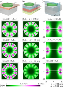
(a) In plane fringe fields h(r) at z = −50 nm (orange plane) for the modes (4, 1, 1), (5, 1, 1), (6, 1, 1). (b) In plane fringe fields h(r) for the mode (6, 1, 1) at depth z = −65 nm, z = −80 nm and z = −95 nm (blue, red and yellow planes, respectively). (c) Fringe fields h(r) for cross section view θ = 0 (blue plane) for modes (4, 1, 1), (5, 1, 1), (6, 1, 1). The white lines delimit the disk dimensions R = 500 nm and d = 100 nm.
Figure 4
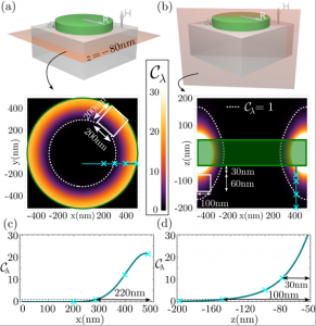
Spatial plot of the cooperativity of the λ = (6, 1, 1) magnon mode (a) at 30 nm below the disk (z = −80 nm), (b) within cross-section plane, (c) along the teal line within (a), (d) along the teal line within (b). The dashed white border shows the strong-coupling regime stability region where Cλ ≥ 1, where the white rectangle indicates a tolerance for spatial implantation imprecision for the NV centers while still achieving high cooperativity. The green lines delimit the disk dimension d = 100 nm and R = 500 nm.
The material is based on work supported by the U.S. Department of Energy, Office of Basic Energy Sciences, under Award Number DE-SC0019250.
Flatté Research Group member Dr. Denis Candido contributed to this work.